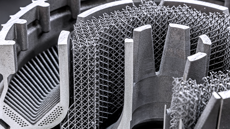
Additive manufacturing (AM) has opened the door to part geometries that were difficult or impossible to produce with conventional manufacturing. Lightweight lattices, internal channels, topology-optimised structures, and consolidated assemblies are now practical design options. For engineers, that freedom creates new opportunities, but it also creates a familiar challenge: how do you know what is happening inside the part?
In AM, the most important features are often not visible from the outside. A part may look acceptable on the surface while containing internal porosity, lack of fusion, trapped powder, cracks, wall-thickness variation, or deviations from the intended CAD geometry. These internal conditions can affect performance, reliability, and process repeatability. They can also be difficult to diagnose with surface inspection, while destructive sectioning is not ideal and what it can reveal is limited.
This is where X-ray computed tomography, commonly called X-ray CT, can play a useful role.
X-ray CT is a non-destructive imaging method that reconstructs a three-dimensional view of a part using many two-dimensional X-ray projections. Instead of seeing only an external surface or a single cross-section, you can inspect internal and external features in 3D. You can review the resulting dataset as cross-sectional slices, render it as a 3D volume, or analyse it quantitatively using specialised software.
For your additive manufacturing work, the value is not simply that CT creates detailed images. The real value is that CT can connect part quality to your design decisions, process parameters, powder condition, and post-processing steps. Used well, it can help you answer practical questions: Where are the pores? How large are they? Are they distributed randomly, or do they follow build layers? Are there blocked channels or trapped powder? Does the printed geometry match the design intent? Is wall thickness consistent across a lattice or thin-walled structure?
Porosity analysis is one of the most common CT applications in AM. Small pores can form through several mechanisms, including lack of fusion and keyhole porosity in laser powder bed fusion. These defects are linked to process conditions such as laser power and scan speed. If energy density is too low, powder may not fully melt, leading to lack-of-fusion porosity. If energy density is too high, an unstable melt pool can trap gas and create keyhole pores. CT helps you see where these pores occur, how they are shaped, and whether they are concentrated in patterns that suggest a process issue.

This is especially useful during process development. CT scans of coupons, rods, density cubes, or witness specimens can show you whether a parameter set is producing acceptable results before you commit to more complex or expensive parts.
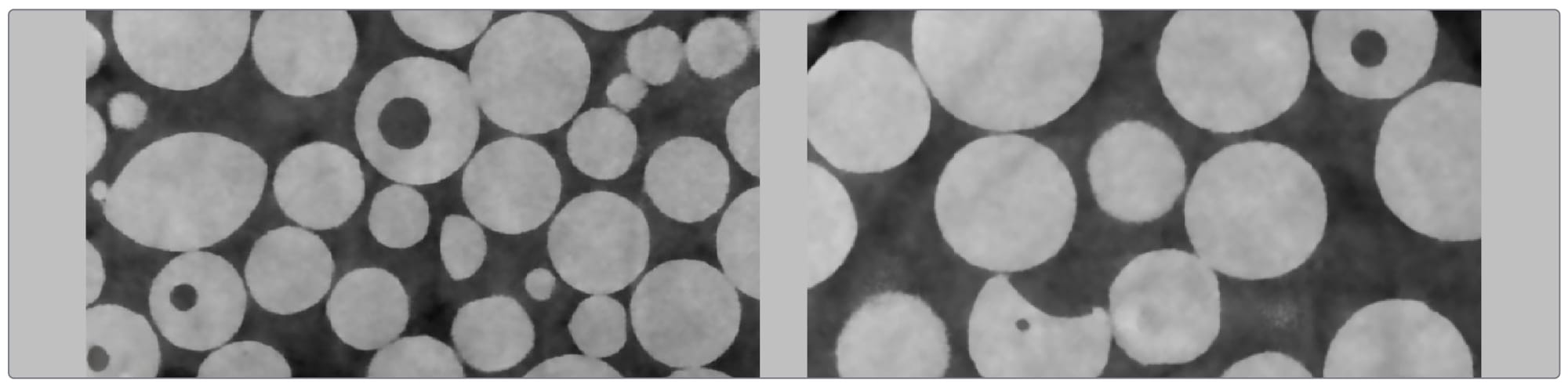
CT can also analyse the feedstock. Feedstock powder quality matters in many AM processes, and irregular particles, internal pores, contamination, and unexpected particle-size distributions can affect build behaviour. Traditional powder characterisation methods provide useful information, but they may miss three-dimensional particle features. CT can reveal pores inside powder particles, non-spherical particles, contamination, and even smaller particles trapped inside larger particles. This can give you another way to investigate inconsistent builds or qualify feedstock changes.
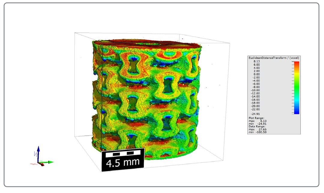
Lattice structures are another strong use case. AM makes it possible to produce intentional macro-porosity through repeated struts, walls, and cellular geometries. These structures can support lightweighting, permeability, energy absorption, and tailored mechanical performance. However, their complexity also makes them difficult to inspect. Lattices may contain trapped powder, micro-porosity inside struts, missing features, rough surfaces, or dimensional deviations. CT allows you to inspect the internal structure without cutting the part apart. It can also support analyses such as wall-thickness measurement, porosity mapping, and comparison between the printed part and the original CAD design.
That design-to-part comparison is often one of the clearest ways to identify the cause of process issues. By aligning CT data to the CAD model, you can visualize where the real part differs from the intended geometry. Color-coded deviation maps can show excess material, missing material, or areas where down-facing surfaces have accumulated dross. This type of visualization can help you identify whether the issue is related to design, orientation, support strategy, process parameters, or post-processing.
CT is also useful in failure analysis. When a printed part fails unexpectedly, destructive sectioning can reveal information at one plane, but it may miss the larger spatial context. CT can show you the location, size, shape, and distribution of defects throughout the part. It can help you determine whether a failure is linked to a localised pore, crack, lack-of-fusion region, trapped powder, thin wall, or geometry deviation. Because the method is non-destructive, the same part can remain available for further testing or documentation.
Although CT can reveal internal details of AM-made parts, you should not treat CT as a sole universal inspection method. Scan time, part size, material density, desired resolution, and analysis workflow all affect the selection of the best analysis tool for the analysis purpose.
The most effective CT work starts with a clear inspection question. Are you looking for major internal flaws, measuring porosity, checking wall thickness, validating lattice quality, comparing the build to CAD, or investigating a failure? Each goal may require a different scan strategy. A quick inspection scan may be enough to find major flaws. A detailed R&D study may require higher resolution, longer scan time, and more analysis effort. The practical value of CT comes from matching the method to the engineering decision you need to make.
To help you understand where CT fits, Rigaku has published a practical CT Solution Guide for AM. The guide explains CT fundamentals, common AM use cases, including powder and porosity analysis, lattice inspection, design comparison, and practical questions to ask before using CT.
Download the CT Solution Guide for Additive Manufacturing to learn how X-ray CT can help you better understand AM parts, diagnose internal features, and improve process decisions.